Norbert Kruissen
Trials Technician


René Bosman
Senior Specialist Mechanical Measurement
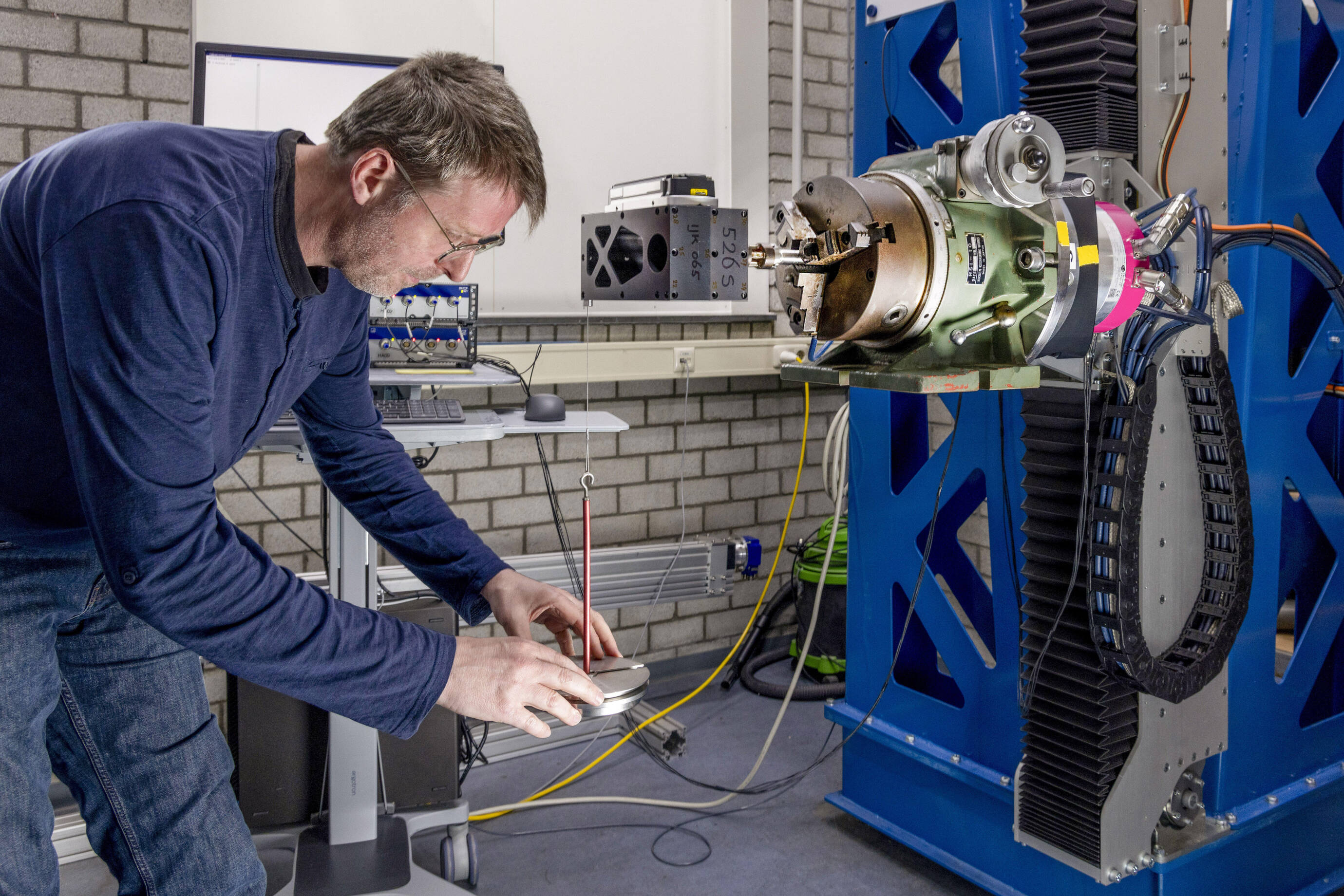
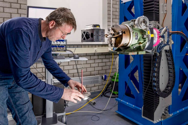
the Z axis.The five-component transducer was calibrated in MARIN’s new calibration setup. In total, 120 load points in 24 different load cases were applied with a very precise machined tool to enable us to assess the forces and moments in several directions.”
Levent Kaydihan
Senior Specialist Hydrostructural Services
January 2026, no. 146
Interested? Contact us to discuss your options
Create a MARIN account to stay updated

Report
Figure 1: First global vertical flexural vibration mode..

Whipping is the transient elastic vibration of the ship’s hull girder which can be caused by slamming for example. For the double-ended ferry, whipping is an important phenomenon to consider when determining design loads. It was therefore necessary to test the ferry using a flexible model.
In order to scale the hull girder flexibility, it is important to represent the shapes and frequencies of the first few global flexural vibration modes. This means that the mass and stiffness distribution of the ship should be adequately represented. For the double-ended ferry modelling, the first vertical global flexural mode illustrated in Figure 1 was deemed sufficient.
A scale model for hydrostructural investigation
If ships become larger, they become more flexible, and this can have an important influence on the design loads of ships. Typically, this means cutting the model into a number of segments and connecting them using a steel or aluminium beam.
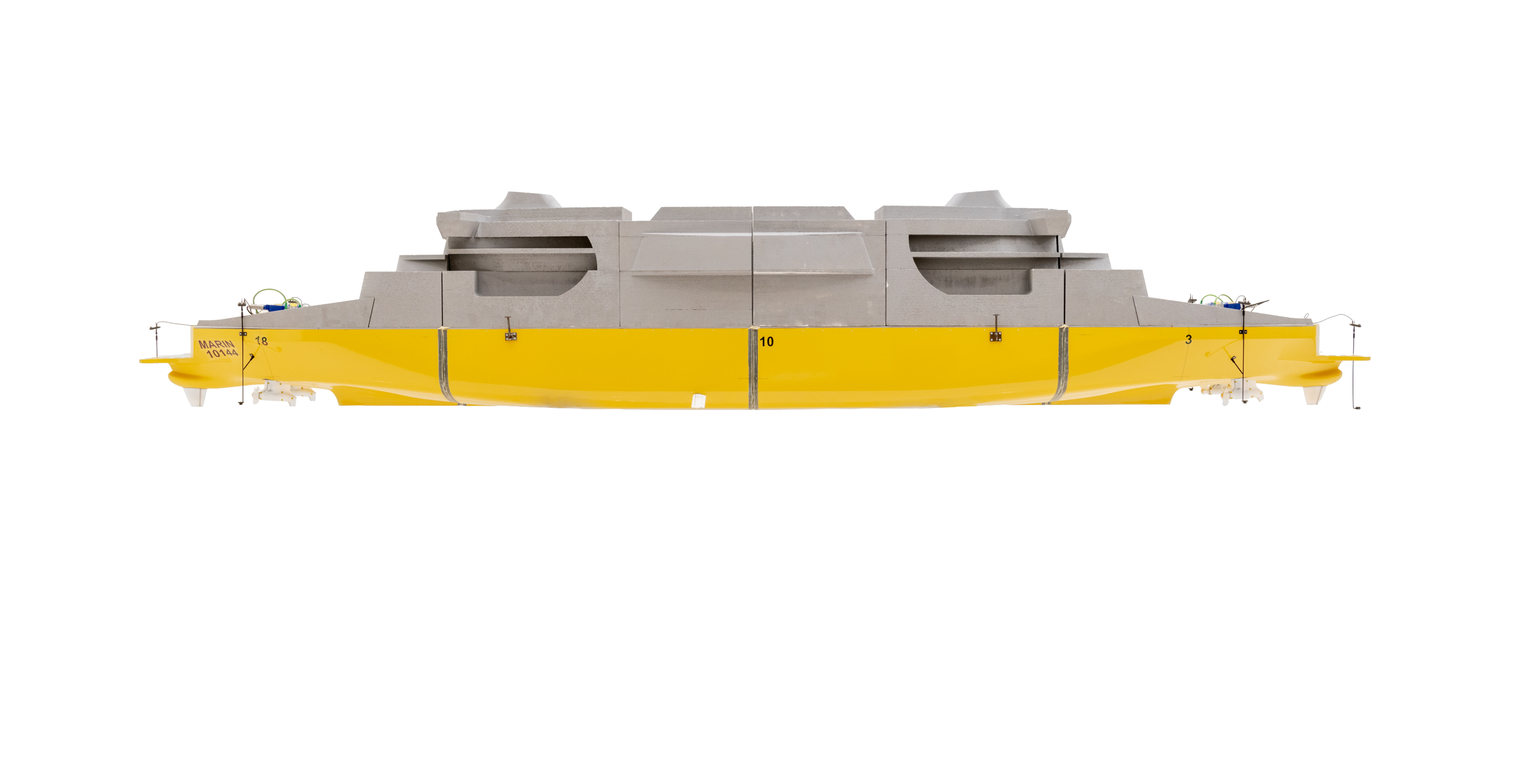
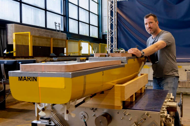
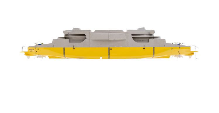
Figure 2: Model split into four segments to represent the shape of the first flexural vibration mode.
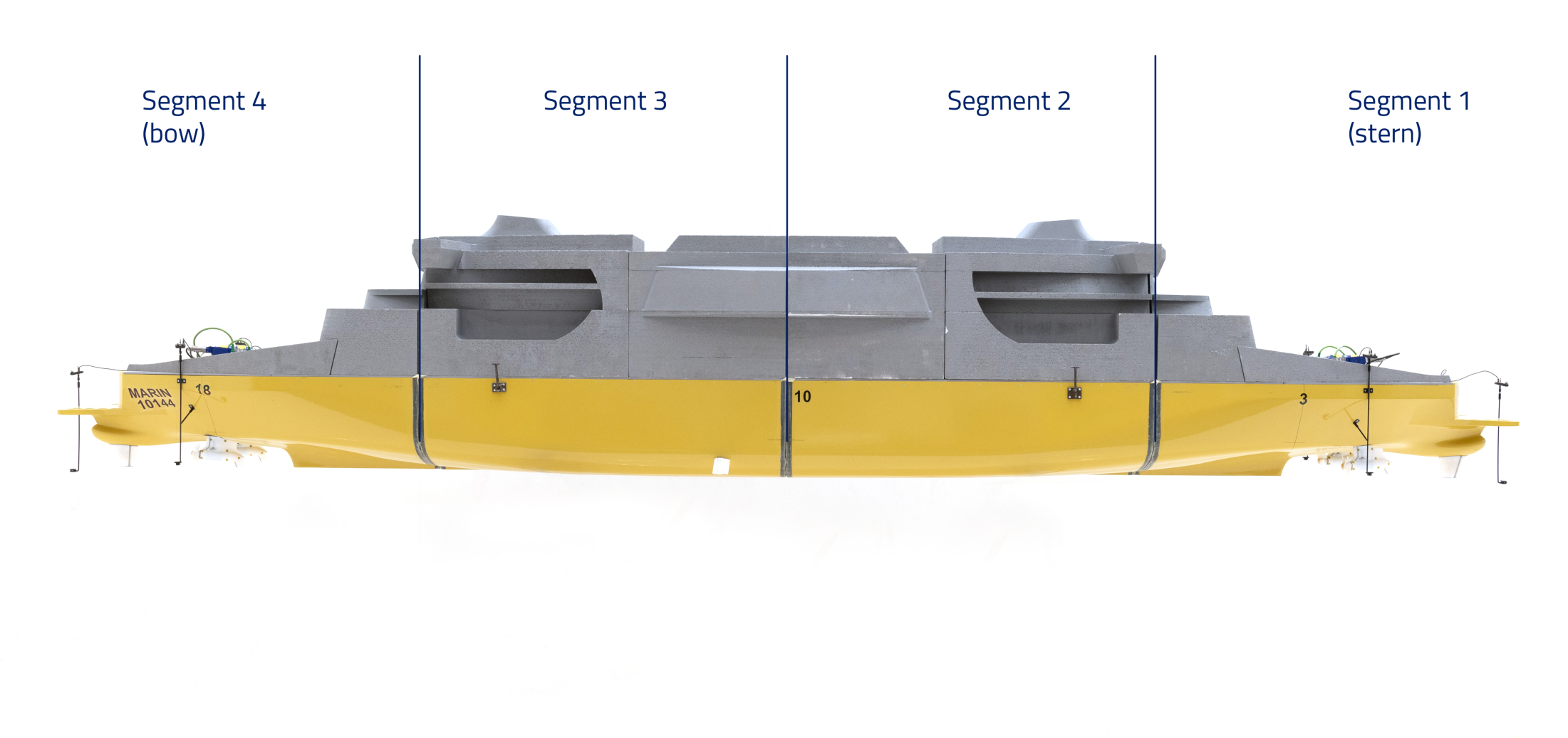

Figure 3: Model on balloons to determine dry natural frequencies.
Flexural behaviour of the pods
As a result of the specific design of this type of ship, the flexural behaviour of the pods under dynamical loads was also assessed. In order to accurately represent the flexural behaviour of the pod, the stiffness of the pod was scaled.
The different mode shapes of the pod depend on the stiffness and inertia in each direction, as well as the mass and added mass. During the feasibility study it became clear that one of our five-component transducers was stiff enough for the pod. Additionally, the inertia of the manufactured scaled pod was within an acceptable range. On top of the five-component transducer, an additional spring element was specially designed by our production team with the aid of FE calculations.
In conclusion, the model was successfully designed and built in a way that accurately reflects the first global vertical flexural vibration mode, as well as the first three vibration modes of one of the pods. Ultimately, this model allowed us to determine the effect of whipping on the design load.
In the next article we outline the model tests used to determine the loads and responses.
Tests in air are therefore preferred. One way to do this is to hang the model in springs. A model consisting of four segments requires 16 springs and although certainly doable, the setup becomes quite cumbersome. However, we found a novel way to determine dry natural frequencies. This was done by placing the model on four large balloons. Figure 3 shows the ferry on the balloons. Information about the shapes and frequencies are again found by applying an impulsive load.
The natural frequencies were determined from eight accelerometers installed over the length of the beam, and four accelerometers installed on the edges of the model. The natural frequency of the second mode was not tuned. However, the two are still in reasonable agreement. Overall, the model is slightly less stiff than the actual ship.
In order to properly represent the shape of the first flexural vibration mode, the model was split into four segments and connected again using an aluminium tube. The distance between the segments is 1cm. The model, with an indication of the four segments, is shown in Figure 2.
Tests in water and air
After designing the flexible beam properties and completing the assembly, the shapes and frequencies of the vibration modes were measured and compared with what was specified. These tests were done both in water and air. Tests in water are carried out by placing the instrumented model in water and exciting it by applying an impulsive load. The disadvantage is that the vibrations of the model also result in the movement of the water. This results in additional mass that is added to the mass of the model. This added mass can be calculated, but it does result in a level of uncertainty.


René Bosman
Senior Specialist Mechanical Measurement
the Z axis.The five-component transducer was calibrated in MARIN’s new calibration setup. In total, 120 load points in 24 different load cases were applied with a very precise machined tool to enable us to assess the forces and moments in several directions.”
Norbert Kruissen
Trials Technician
January 2026, no. 146
Flexural behaviour of the pods
As a result of the specific design of this type of ship, the flexural behaviour of the pods under dynamical loads was also assessed. In order to accurately represent the flexural behaviour of the pod, the stiffness of the pod was scaled.
The different mode shapes of the pod depend on the stiffness and inertia in each direction, as well as the mass and added mass. During the feasibility study it became clear that one of our five-component transducers was stiff enough for the pod. Additionally, the inertia of the manufactured scaled pod was within an acceptable range. On top of the five-component transducer, an additional spring element was specially designed by our production team with the aid of FE calculations.
In conclusion, the model was successfully designed and built in a way that accurately reflects the first global vertical flexural vibration mode, as well as the first three vibration modes of one of the pods. Ultimately, this model allowed us to determine the effect of whipping on the design load.
In the next article we outline the model tests used to determine the loads and responses.
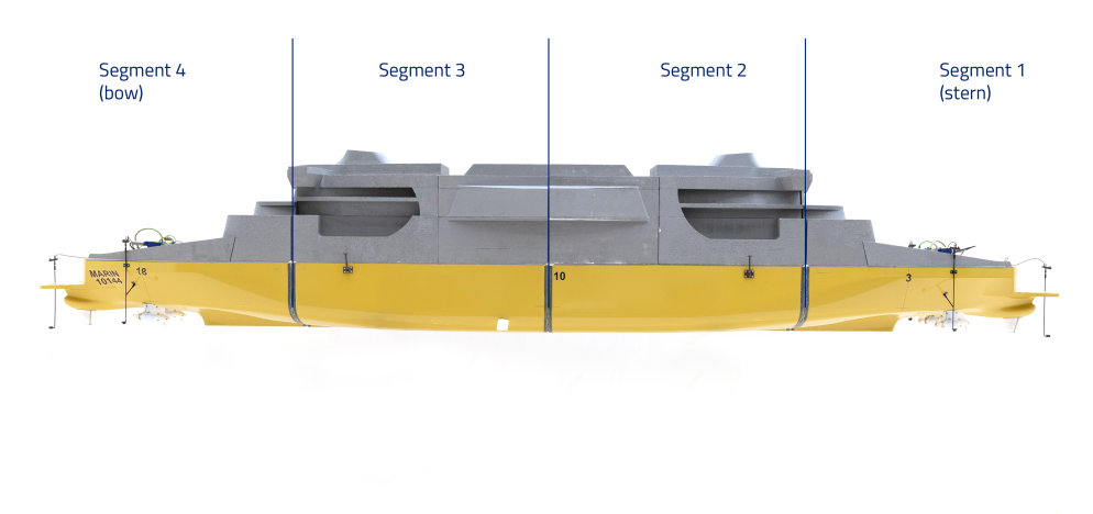
Figure 2: Model split into four segments to represent the shape of the first flexural vibration mode.
Figure 1: First global vertical flexural vibration mode..
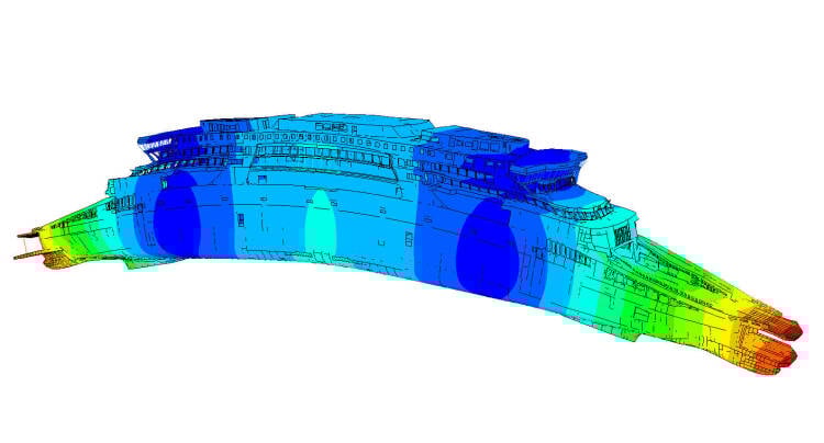
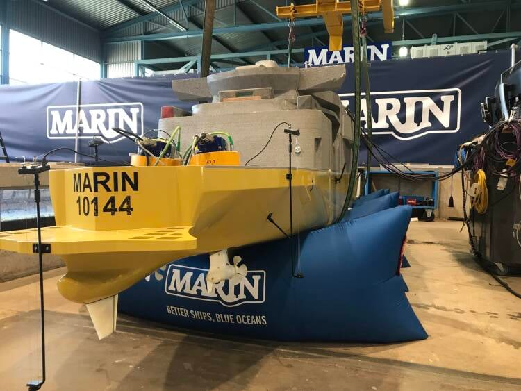
Figure 3: Model on balloons to determine dry natural frequencies.
Tests in air are therefore preferred. One way to do this is to hang the model in springs. A model consisting of four segments requires 16 springs and although certainly doable, the setup becomes quite cumbersome. However, we found a novel way to determine dry natural frequencies. This was done by placing the model on four large balloons. Figure 3 shows the ferry on the balloons. Information about the shapes and frequencies are again found by applying an impulsive load.
The natural frequencies were determined from eight accelerometers installed over the length of the beam, and four accelerometers installed on the edges of the model. The natural frequency of the second mode was not tuned. However, the two are still in reasonable agreement. Overall, the model is slightly less stiff than the actual ship.
Ingo Drummen
Senior Project Manager
Levent Kaydihan
Senior Specialist Hydrostructural Services

In order to properly represent the shape of the first flexural vibration mode, the model was split into four segments and connected again using an aluminium tube. The distance between the segments is 1cm. The model, with an indication of the four segments, is shown in Figure 2.
Tests in water and air
After designing the flexible beam properties and completing the assembly, the shapes and frequencies of the vibration modes were measured and compared with what was specified. These tests were done both in water and air. Tests in water are carried out by placing the instrumented model in water and exciting it by applying an impulsive load. The disadvantage is that the vibrations of the model also result in the movement of the water. This results in additional mass that is added to the mass of the model. This added mass can be calculated, but it does result in a level of uncertainty.
Whipping is the transient elastic vibration of the ship’s hull girder which can be caused by slamming for example. For the double-ended ferry, whipping is an important phenomenon to consider when determining design loads. It was therefore necessary to test the ferry using a flexible model.
In order to scale the hull girder flexibility, it is important to represent the shapes and frequencies of the first few global flexural vibration modes. This means that the mass and stiffness distribution of the ship should be adequately represented. For the double-ended ferry modelling, the first vertical global flexural mode illustrated in Figure 1 was deemed sufficient.
A scale model for hydrostructural investigation
If ships become larger, they become more flexible, and this can have an important influence on the design loads of ships. Typically, this means cutting the model into a number of segments and connecting them using a steel or aluminium beam.


Interested? Contact us to discuss your options
Report
Create a MARIN account to stay updated