Conceptual Design and Verification of the Power, Propulsion, and Energy System for a Future Surface Combatant, B. Moritz Krijgsman et al., IMarEST Conference Paper INEC 2024
Systems Engineering for Naval Ship Design Evolution, Mattia Bottero et al., Journal of Marine Science and Engineering 2024
Basic Design Concepts, J. Harvey Evans, Naval Engineers Journal, Nov 1959
More info

Co-design and Energy Management for Future Vessels, Steven Wilkins et al., Moses Conference Paper, 2023

The Zero Emission Lab is a unique test facility worldwide for the research and testing of future marine propulsion and power systems.
August 2026, no. 148




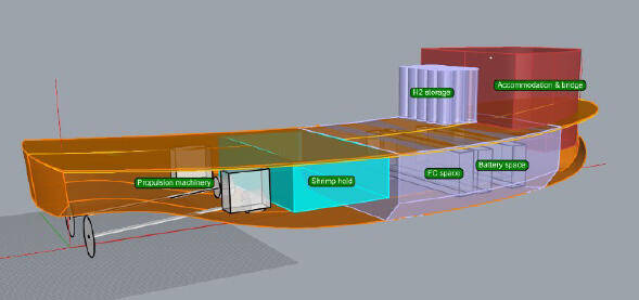
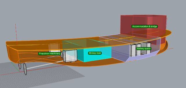
Figure 3. Two variants of the first conceptual design of the ship: the battery electric variant (above) and the fuel cell electric variant (below).

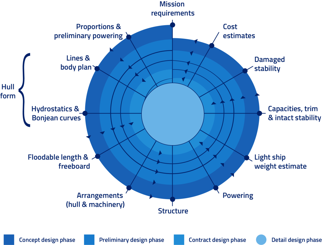
Figure 1. Design spiral of ship design.
The ship design spiral
As long as ships have been designed, they have followed a design spiral. Figure 1. shows a flattened picture of a design spiral for ships. The ‘stations’ around the outline are addressed in every ‘winding’ spiral with increasing fidelity, until finally sufficient accuracy is achieved for starting the detailed engineering.
The ‘spiral design path’ must be followed in order to keep all parties informed, especially the stakeholders who have interests in non-technical aspects. For the design team, this approach provides multidisciplinary insight, e.g. ‘Why is the design of the hull influenced so much by the selection of the power, propulsion and energy system?’
Create a MARIN account to stay updated

Report
Innovative government project to develop new sustainable shrimp cutter
In close co-operation with stakeholders and design partners, MARIN is carrying out a development and design project for a new sustainable shrimp cutter on behalf of the Dutch Ministry of Agriculture, Fisheries, Food Security and Nature.
Progress of the concept design
At this moment the requirements for the vessel are set, but technological impossibilities coming from the concept design could lead to their reconsideration, for example, caused by the result of a virtual test. Two variants of the first conceptual design of the ship are shown in
Figure 3. The battery electric variant is shown above and the fuel cell electric variant below.
Because of simplicity, there is a preference for the battery electric variant, but it is questionable whether all operational requirements can be met. The battery might become too large and too heavy. If this is the case, then this would mean a review of the requirements and a search for an alternative technology, which could result in the fuel cell electric variant being chosen.
W model for virtual verification of the design
Using MBSE provides the possibility of extending the conventional V model with an extra preceding V that represents the digital model cycle. This results in a W model. The use of model-based simulation and testing methods throughout the lifecycle of a vessel, from early-stage design to deployment and commissioning, is visualised by the W model, as shown in Figure 2. The virtual models can be used to verify whether the designs meet system requirements, in Figure 2. referred to as the arrow ‘digital design verification’. Furthermore, the digital models can be used to refine designs and through digital twinning, these models can serve to optimise the ship and its operations.
The properties of the virtual models, test cases and test results are recorded in the MBSE model.
The common goal is to mitigate project risks. The spiral design approach means that every winding has its own needs concerning the fidelity and accuracy of design data. Stakeholders and designers must constantly be aware of the purpose of the data. A conceptual ship length of 20 m is sufficient when it is accompanied by the constraints, for example, the ship length should not exceed 24 m or not be less than 16 m. In the next ‘windings’ of the design spiral the conceptual data will be refined.
The properties of the requirements and design data are guarded in the MBSE model. At this moment the sustainable shrimp cutter is in the second half of the first winding - ‘concept design’.
Additionally, the data required for executing tasks and having discussions must be common and used by all parties. Here the team uses model-based systems engineering (MBSE). This creates a ‘single source of truth’ and ‘traceability from requirements to technical solutions and vice versa’.
During the concurrent design sessions, lively discussions come up concerning the origin and fidelity of requirements and design data. This article focuses on combining the modern methods of concurrent design and MBSE with the conventional ship design spiral.
The objectives of this multifaceted project are based on two key principles: that the shrimp cutter won’t produce exhaust emissions, and that it should feature a more sustainable hull material than the steel currently used. TNO, the Netherlands Organisation for Applied Scientific Research, is responsible for the material design aspects together with the industry.
No exhaust emissions and an alternative to steel
Given the project’s complexity, it is crucial that all the stakeholders and designers are constantly involved in the very dynamic process of conceiving and setting the requirements and evaluating possible technical solutions. This is done by introducing a process of concurrent design.
The fishing industry is under political and societal pressure to become more sustainable. Coastal fishing, in particular—whether or not it takes place in Natura 2000 areas—faces strict requirements regarding its environmental impact, such as significantly reducing exhaust emissions.
These sustainability goals also apply to shrimp fishery that is primarily operated by small businesses, which have limited capital for major investments and low risk tolerance for further sustainability measures.
Interested? Contact us to discuss your options
“This collaboration exemplifies how we translate sustainability ambitions into tangible solutions—from concept to operation.”

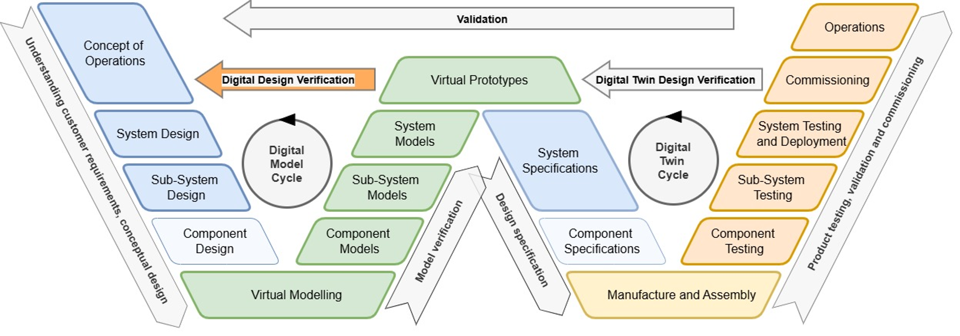
Figure 2. W model for (virtual) verification of the design.


Conceptual Design and Verification of the Power, Propulsion, and Energy System for a Future Surface Combatant, B. Moritz Krijgsman et al., IMarEST Conference Paper INEC 2024
Systems Engineering for Naval Ship Design Evolution, Mattia Bottero et al., Journal of Marine Science and Engineering 2024
Basic Design Concepts, J. Harvey Evans, Naval Engineers Journal, Nov 1959
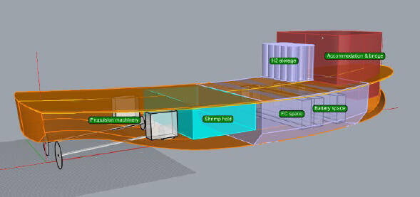
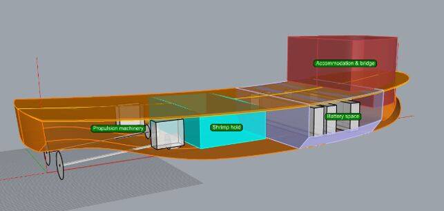
Figure 3. Two variants of the first conceptual design of the ship: the battery electric variant (above) and the fuel cell electric variant (below).
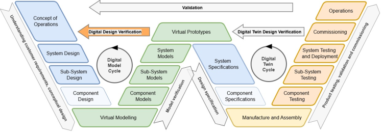
Figure 2. W model for (virtual) verification of the design.
W model for virtual verification of the design
Using MBSE provides the possibility of extending the conventional V model with an extra preceding V that represents the digital model cycle. This results in a W model. The use of model-based simulation and testing methods throughout the lifecycle of a vessel, from early-stage design to deployment and commissioning, is visualised by the W model, as shown in Figure 2. The virtual models can be used to verify whether the designs meet system requirements, in Figure 2. referred to as the arrow ‘digital design verification’. Furthermore, the digital models can be used to refine designs and through digital twinning, these models can serve to optimise the ship and its operations.
The properties of the virtual models, test cases and test results are recorded in the MBSE model.
The common goal is to mitigate project risks. The spiral design approach means that every winding has its own needs concerning the fidelity and accuracy of design data. Stakeholders and designers must constantly be aware of the purpose of the data. A conceptual ship length of 20 m is sufficient when it is accompanied by the constraints, for example, the ship length should not exceed 24 m or not be less than 16 m. In the next ‘windings’ of the design spiral the conceptual data will be refined.
The properties of the requirements and design data are guarded in the MBSE model. At this moment the sustainable shrimp cutter is in the second half of the first winding - ‘concept design’.
The ship design spiral
As long as ships have been designed, they have followed a design spiral. Figure 1. shows a flattened picture of a design spiral for ships. The ‘stations’ around the outline are addressed in every ‘winding’ spiral with increasing fidelity, until finally sufficient accuracy is achieved for starting the detailed engineering.
The ‘spiral design path’ must be followed in order to keep all parties informed, especially the stakeholders who have interests in non-technical aspects. For the design team, this approach provides multidisciplinary insight, e.g. ‘Why is the design of the hull influenced so much by the selection of the power, propulsion and energy system?’
“This collaboration exemplifies how we translate sustainability ambitions into tangible solutions—from concept to operation.”
August 2026, no. 148
Co-design and Energy Management for Future Vessels, Steven Wilkins et al., Moses Conference Paper, 2023
Additionally, the data required for executing tasks and having discussions must be common and used by all parties. Here the team uses model-based systems engineering (MBSE). This creates a ‘single source of truth’ and ‘traceability from requirements to technical solutions and vice versa’.
During the concurrent design sessions, lively discussions come up concerning the origin and fidelity of requirements and design data. This article focuses on combining the modern methods of concurrent design and MBSE with the conventional ship design spiral.
The objectives of this multifaceted project are based on two key principles: that the shrimp cutter won’t produce exhaust emissions, and that it should feature a more sustainable hull material than the steel currently used. TNO, the Netherlands Organisation for Applied Scientific Research, is responsible for the material design aspects together with the industry.
No exhaust emissions and an alternative to steel
Given the project’s complexity, it is crucial that all the stakeholders and designers are constantly involved in the very dynamic process of conceiving and setting the requirements and evaluating possible technical solutions. This is done by introducing a process of concurrent design.
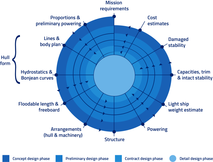
Figure 1. Design spiral of ship design.
The fishing industry is under political and societal pressure to become more sustainable. Coastal fishing, in particular—whether or not it takes place in Natura 2000 areas—faces strict requirements regarding its environmental impact, such as significantly reducing exhaust emissions.
These sustainability goals also apply to shrimp fishery that is primarily operated by small businesses, which have limited capital for major investments and low risk tolerance for further sustainability measures.
In close co-operation with stakeholders and design partners, MARIN is carrying out a development and design project for a new sustainable shrimp cutter on behalf of the Dutch Ministry of Agriculture, Fisheries, Food Security and Nature.
Innovative government project to develop new sustainable shrimp cutter
Progress of the concept design
At this moment the requirements for the vessel are set, but technological impossibilities coming from the concept design could lead to their reconsideration, for example, caused by the result of a virtual test. Two variants of the first conceptual design of the ship are shown in
Figure 3. The battery electric variant is shown above and the fuel cell electric variant below.
Because of simplicity, there is a preference for the battery electric variant, but it is questionable whether all operational requirements can be met. The battery might become too large and too heavy. If this is the case, then this would mean a review of the requirements and a search for an alternative technology, which could result in the fuel cell electric variant being chosen.
Interested? Contact us to discuss your options
Create a MARIN account to stay updated

Report