Report
April 2023, no. 135

Create a MARIN account to stay updated
Within the JoRes JIP, unique full-scale wake field measurements were performed with MARIN’s new flow velocity measurement device called the ‘FlowPike’. This is the first time MARIN has investigated flow around a full-scale ship with such a precise level of detail and it offers valuable insights into scale effects, as well as high quality data that can be used for comparisons with results from CFD simulations.

Trial runs conducted at night
After the ship was scanned, the speed/power trial equipment was installed. This consisted of a shaft torque and RPM meters to measure the shaft power, a DGPS unit to measure the vessel position, speed and heading, an ultrasonic anemometer for obtaining wind speed and direction, a wave buoy deployed to gather wave statistics and directional wave spectra and a motion sensor. In addition, the water temperature and density, and the air temperature, pressure and humidity were measured during the trial. Finally, the vessel draught was measured at sea at multiple locations on the ship.
The trial runs were performed in 2022 in the Persian Gulf according to ISO15016:2015. In total, six double runs were conducted for four different vessel speeds (RPMs) in one night. The trial conditions were very favourable, with low wind and waves.
Exceptional data set
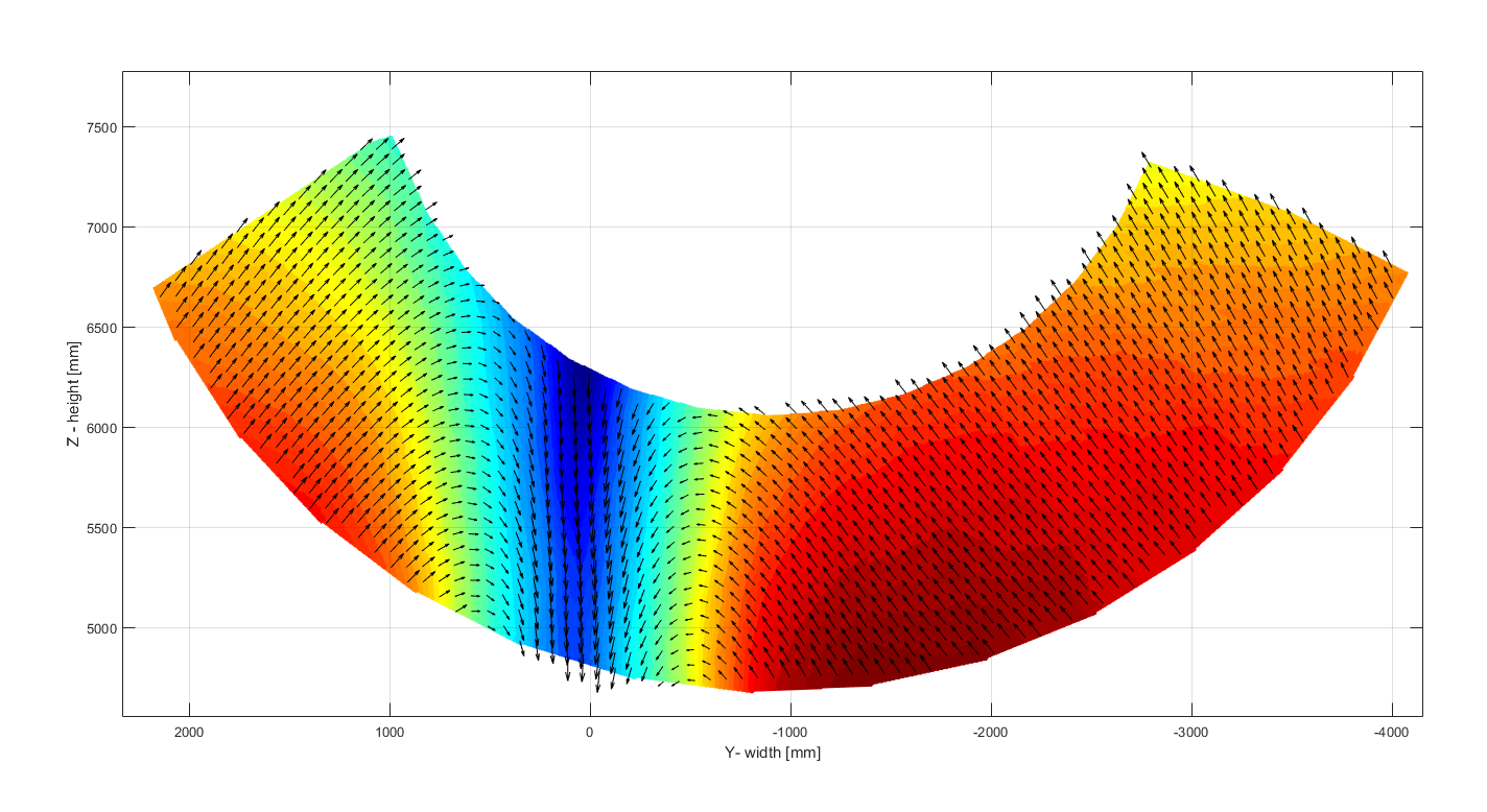
An example flow field measured by the FlowPike is shown in figure 3. As the results are currently part of a blind CFD validation study within the JoRes project, the velocity scale is not shown. The axes show the spatial dimensions, and it can be seen that the entire velocity field is more than 6 m wide and approximately 2.5 m high. This is a substantial area that includes the ship wake, visible as a velocity deficit at y-coordinate zero. The colours show the velocity component perpendicular to the measurement plane, while the vectors show the in-plane velocity components. These present two vortices on the sides of the wake, as expected from model scale studies and previous CFD calculations. Overall, the high resolution and accuracy of the present PIV results, complemented by a comprehensive set of quantities measured as part of the speed/power trial make the current data set exceptional. We are looking forward to the new insights and the improvements of the CFD codes that this data will bring, as well as to applying the FlowPike on other ships in the future.
An unusual aspect of the present trials is that they were conducted at night. This was important in order to reduce the amount of ambient light coming into the FlowPike. Excessive ambient light would disturb the measurements, since the FlowPike is a device that applies an optical flow measurement technique called Particle Image Velocimetry (PIV). This technique uses two cameras and a laser light source encased in a housing fixed to the hull above the propeller. The laser emits light in the form of a sheet and illuminates particles that are naturally present in the sea. The particle images are recorded by the cameras, after which the recorded images are processed to arrive at instantaneous flow fields in a rectangular area 1.4 m long and 0.6 m wide (see figure 2). The flow fields are recorded at a frequency of 10 Hz and each field is composed of thousands of 3D velocity vectors. In addition, the FlowPike can rotate around its longitudinal axis, thereby extending the total inflow that is measured during one run. This is done by stitching the individual averaged fields into one large, fan-shaped field.
Figure 2. View from the stern towards the bow. The individual flow fields are shown as red rectangular areas. The total velocity field is made by stitching the individual fields into a large, fan-shaped area.
Figure 3. An example velocity field. The colour represents the out-of-plane velocity component (in the direction of ship movement), while the vectors represent the in-plane velocities. The zero point is at the ship’s baseline, centreline and at station zero (height, width, length).
The JoRes JIP group is made up of 50 industrial partners spanning the entire shipping industry which have a common interest in improving their ability to predict ship performance using computational tools. Within the project, there have been several model testing campaigns, full-scale trials and calculations performed using in-house and commercial CFD tools.
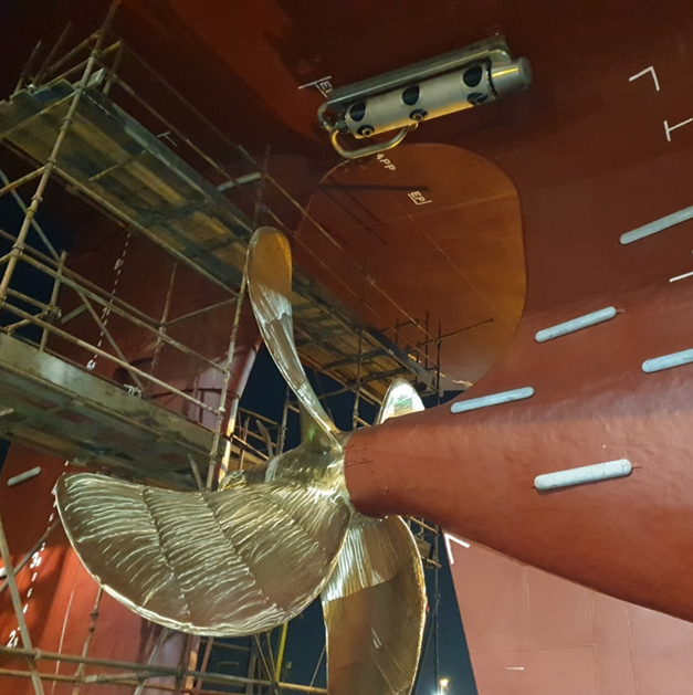
One of the trials was performed on a modern 50,000 DWT tanker (see figure 1). Before the trial, permission was obtained from the hull and propeller designers to make their designs public. The propeller and hull were then laser scanned to obtain the ‘as built’ geometry of the vessel and the roughness was measured as well. All the measured data (geometry, roughness, speed/power trial results and propeller inflow velocity fields) will become part of a dataset that can be used in highly accurate CFD benchmark studies in the future.
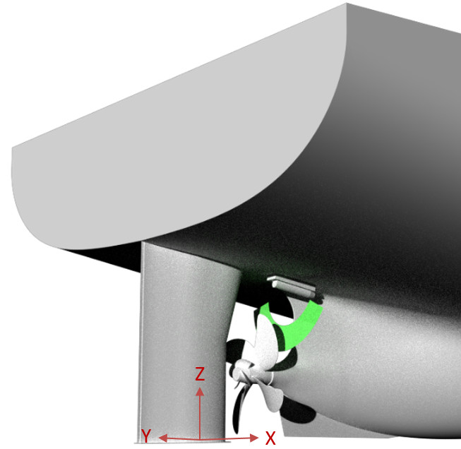
Figure 1. The FlowPike fixed to the hull above the propeller. The laser and camera controls are in a pipe connected to the equipment through an opening in the hull.

More info:
The Joint Industry Project JoRes is the first project in which full-scale wake field measurements were performed with the FLowPike objective of this Joint Research project (JoRes JIP)


Miloš Birvalski
Specialist Performance at Sea


Gijs Struijk
Project Manager Performance at Sea


April 2023, no. 135
Gijs Struijk
Project Manager Performance at Sea
Miloš Birvalski
Specialist Performance at Sea
The Joint Industry Project JoRes is the first project in which full-scale wake field measurements were performed with the FLowPike objective of this Joint Research project (JoRes JIP)
More info:
Exceptional data set
An example flow field measured by the FlowPike is shown in figure 3. As the results are currently part of a blind CFD validation study within the JoRes project, the velocity scale is not shown. The axes show the spatial dimensions, and it can be seen that the entire velocity field is more than 6 m wide and approximately 2.5 m high. This is a substantial area that includes the ship wake, visible as a velocity deficit at y-coordinate zero. The colours show the velocity component perpendicular to the measurement plane, while the vectors show the in-plane velocity components. These present two vortices on the sides of the wake, as expected from model scale studies and previous CFD calculations. Overall, the high resolution and accuracy of the present PIV results, complemented by a comprehensive set of quantities measured as part of the speed/power trial make the current data set exceptional. We are looking forward to the new insights and the improvements of the CFD codes that this data will bring, as well as to applying the FlowPike on other ships in the future.
An unusual aspect of the present trials is that they were conducted at night. This was important in order to reduce the amount of ambient light coming into the FlowPike. Excessive ambient light would disturb the measurements, since the FlowPike is a device that applies an optical flow measurement technique called Particle Image Velocimetry (PIV). This technique uses two cameras and a laser light source encased in a housing fixed to the hull above the propeller. The laser emits light in the form of a sheet and illuminates particles that are naturally present in the sea. The particle images are recorded by the cameras, after which the recorded images are processed to arrive at instantaneous flow fields in a rectangular area 1.4 m long and 0.6 m wide (see figure 2). The flow fields are recorded at a frequency of 10 Hz and each field is composed of thousands of 3D velocity vectors. In addition, the FlowPike can rotate around its longitudinal axis, thereby extending the total inflow that is measured during one run. This is done by stitching the individual averaged fields into one large, fan-shaped field.

Figure 2. View from the stern towards the bow. The individual flow fields are shown as red rectangular areas. The total velocity field is made by stitching the individual fields into a large, fan-shaped area.
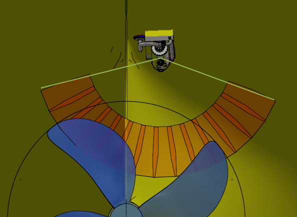
Figure 3. An example velocity field. The colour represents the out-of-plane velocity component (in the direction of ship movement), while the vectors represent the in-plane velocities. The zero point is at the ship’s baseline, centreline and at station zero (height, width, length).

Trial runs conducted at night
After the ship was scanned, the speed/power trial equipment was installed. This consisted of a shaft torque and RPM meters to measure the shaft power, a DGPS unit to measure the vessel position, speed and heading, an ultrasonic anemometer for obtaining wind speed and direction, a wave buoy deployed to gather wave statistics and directional wave spectra and a motion sensor. In addition, the water temperature and density, and the air temperature, pressure and humidity were measured during the trial. Finally, the vessel draught was measured at sea at multiple locations on the ship.
The trial runs were performed in 2022 in the Persian Gulf according to ISO15016:2015. In total, six double runs were conducted for four different vessel speeds (RPMs) in one night. The trial conditions were very favourable, with low wind and waves.
The JoRes JIP group is made up of 50 industrial partners spanning the entire shipping industry which have a common interest in improving their ability to predict ship performance using computational tools. Within the project, there have been several model testing campaigns, full-scale trials and calculations performed using in-house and commercial CFD tools.
One of the trials was performed on a modern 50,000 DWT tanker (see figure 1). Before the trial, permission was obtained from the hull and propeller designers to make their designs public. The propeller and hull were then laser scanned to obtain the ‘as built’ geometry of the vessel and the roughness was measured as well. All the measured data (geometry, roughness, speed/power trial results and propeller inflow velocity fields) will become part of a dataset that can be used in highly accurate CFD benchmark studies in the future.
Figure 1. The FlowPike fixed to the hull above the propeller. The laser and camera controls are in a pipe connected to the equipment through an opening in the hull.
Within the JoRes JIP, unique full-scale wake field measurements were performed with MARIN’s new flow velocity measurement device called the ‘FlowPike’. This is the first time MARIN has investigated flow around a full-scale ship with such a precise level of detail and it offers valuable insights into scale effects, as well as high quality data that can be used for comparisons with results from CFD simulations.
Report