News
Shallow water
EEXI
Wind propulsion
Turbulent breakthrough
CFD VIM
Floating Wind
Shortsea shipping
Cover
Create a MARIN account to stay updated


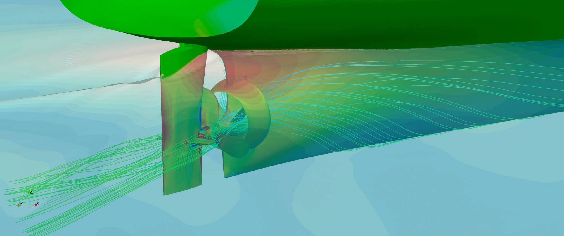
Figure 7. Extract of STAIMO report for the 55K dwt bulk carrier retrofitted with a 3-blade propeller, Becker Mewis Duct and low friction coating. The averaged corrected points from the sea trials are shown in black. The corresponding CFD predictions are indicated by “PS model” by the light dashed grey curves.
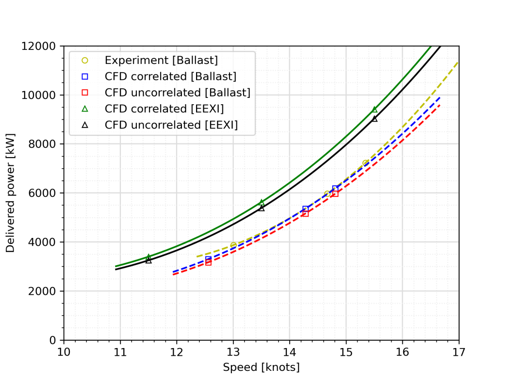
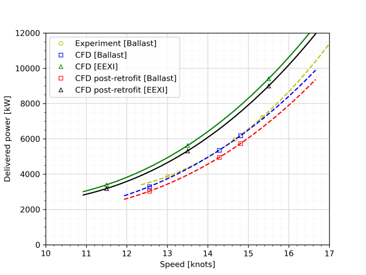
Figure 6. CFD speed-power curves pre- and post-retrofit at both ballast and EEXI loading condition.
Figure 5. CFD visualisation of the vessel post-retrofit in ballast loading condition.
Figure 3. CFD speed-power curves correlated with sea trial data at ballast loading condition

[1] IACS, "Development of draft 2022 IACS guidelines for the use of computational fluid dynamics for the purposes of deriving the Vref in the framework of the EEXI regulation."
December 2023, no. 138


Report
As an independent hydrodynamic research institute, MARIN provides advice and clarity on energy saving solutions and energy efficiency.
Since 1 January 2023, the International Maritime Organization (IMO) demands that all ships have their EEXI calculated. Simply put, the EEXI regulates carbon emissions for ships, whilst continuing to meet speed and cargo requirements (more details). To improve the EEXI, existing ships can often benefit from improvements to their energy efficiency.
The first question that typically arises concerns the potential of retrofit solutions: What can be done on my vessel and what power/fuel savings can I expect? For this, MARIN proposes a cost-effective retrofit scan conducted in two to three days in which possible retrofit solutions are highlighted.
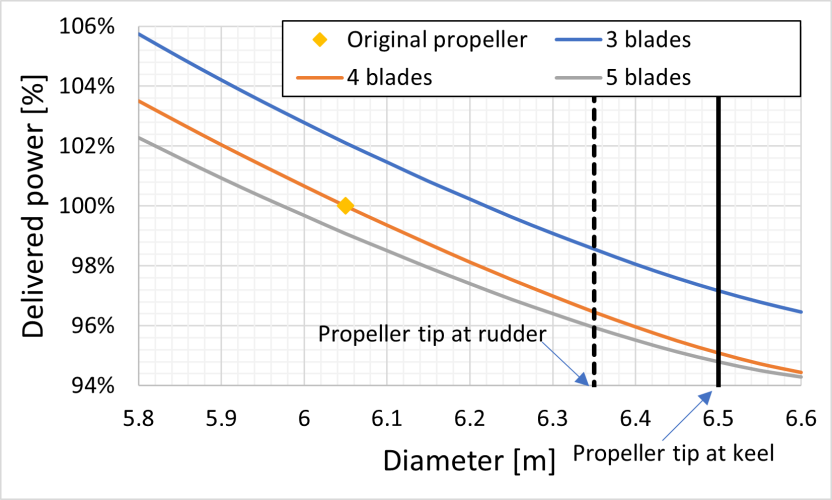
Figure 1. Example of a propeller diameter and number of blades optimisation.

Retrofit solutions
During a retrofit scan, the existing propeller of the vessel is analysed and benchmarked against the latest Wageningen F-series propellers. Often the efficiency of the propeller can be improved with a modern propeller design. Also, the engine power limitations introduced on the vessel often means that 1 to 2% efficiency gains can be achieved. Moreover, substantial power savings are possible by changing the propeller diameter and number of blades, while maintaining keel clearance and cavitation level, see example in Figure 1
Despite MARIN’s efforts to deliver state-of-the-art CFD, it is good to remain critical and question whether the savings predicted by CFD are also observed on board the vessel. Some shipowners, as in the case of the 55K dwt bulk carrier, are fortunately keen on having this question answered by conducting sea trials post-retrofit. The result is illustrated in Figure 7 (extract from STAIMO report). The vessel post-retrofit was painted with a low friction coating estimated to reduce the power by about 2 to 3% at an equal speed which was not included in the CFD predictions. As shown in Figure 7, an excellent agreement is obtained between CFD predictions and sea trial measurements.
All in all, this is certainly a successful project right from the retrofit scan study, all the way to the CFD evaluations. MARIN is ready and looking forward to the (your?) next vessel!
Power savings for a 55K dwt bulk carrier
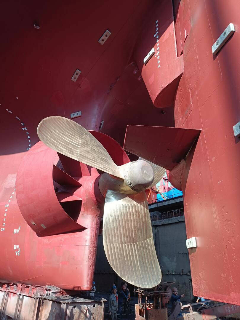
An example of a CFD speed-power curve based on the 55K dwt bulk carrier previously mentioned is illustrated in Figure 3. The original sea trial data, indicated by the yellow dashed line in Figure 3, are used to correlate the CFD predictions. When no retrofit solution is selected the results from Figure 3 are sufficient for the EEXI. For this particular vessel however, a new 3-bladed propeller from Wartsila, as well as a Becker Mewis Duct (BMD), were installed which required CFD computations post-retrofit. Views of the vessel in the drydock after installation of the new propeller and BMD are shown in Figure 4. The same vessel evaluated by CFD is shown in Figure 5. The CFD predictions pre- and post-retrofit are presented in Figure 6. The savings predicted by the retrofit scan study are found in the CFD simulations. At ballast loading condition, average power savings of 7.6% are found while at EEXI loading condition 5.3% savings are possible at an equal ship speed.
Finally, each ship requires an EEXI technical file for which several parameters are required. One on this parameter is reference speed Vref. This can be calculated from the formula in the IMO resolution MEPC.333(76), albeit this approach is not accurate nor advantageous for the EEXI. Alternatively, tank tests or sea trials can be conducted to derive Vref, although the costs involved are not insignificant. Instead, MARIN proposes to use a CFD speed-power curve to derive this reference speed. The CFD speed power curve is obtained using MARIN’s CFD code ReFRESCO and in agreement with the guidelines from the IACS [1]
Besides the propeller, other hydrodynamic aspects are considered in the scan such as energy saving devices (ESDs) or the shape of the (bulbous) bow in relation to the operational profile of the vessel. As an example, a retrofit scan was performed for a 55K dwt bulk carrier built in 2005 on behalf of Azolla, which is the decarbonisation branch of Synergy Maritime Group. The scan concluded that 7% power savings can be achieved with the combination of a new propeller design and a pre swirl device. Further smaller improvements can also be gained by installing a rudder bulb or boss cap fins to eliminate the propeller hub vortex for example.
Once the retrofit solutions are identified, MARIN provides support in the design phase on the hydrodynamic aspects. This support can be a propeller optimisation which can be conducted in two weeks. The propeller is (re)designed based on an effective wake field obtained behind the vessel including, when present, ESDs such as a pre swirl stator duct. Propeller performance is evaluated in terms of cavitation behaviour, efficiency and strength requirements as illustrated in Figure 2 (more details). All dots in the Figure represent a propeller. As the optimisation advances, better propellers are created. This is highlighted, with the earlier designs in blue to the latest ones in red.
Figure 2. Example of optimisation case with final Pareto front in red. Both the margin against cavitation and efficiency were maximised. The red lines indicate the original propeller.
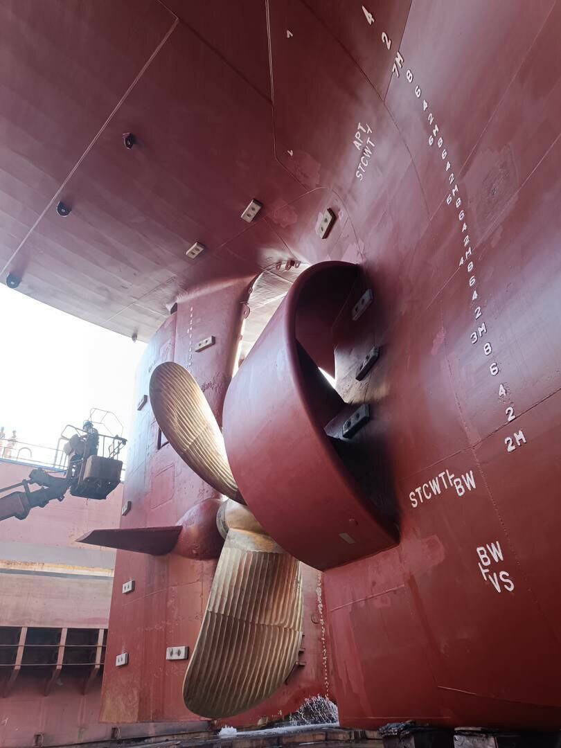
Figure 4. Photographs of the 55k dwt bulk carrier retrofitted with new 3-blade propeller and Becker Mewis Duct (Picture Azolla).
Mukesh Keni
Head Technical Projects of Azolla


Maxime Garenaux
Project Manager Ships


More info


Maxime Garenaux
Project Manager Ships
[1] IACS, "Development of draft 2022 IACS guidelines for the use of computational fluid dynamics for the purposes of deriving the Vref in the framework of the EEXI regulation."
Mukesh Keni
Head Technical Projects of Azolla
Figure 6. CFD speed-power curves pre- and post-retrofit at both ballast and EEXI loading condition.
Despite MARIN’s efforts to deliver state-of-the-art CFD, it is good to remain critical and question whether the savings predicted by CFD are also observed on board the vessel. Some shipowners, as in the case of the 55K dwt bulk carrier, are fortunately keen on having this question answered by conducting sea trials post-retrofit. The result is illustrated in Figure 7 (extract from STAIMO report). The vessel post-retrofit was painted with a low friction coating estimated to reduce the power by about 2 to 3% at an equal speed which was not included in the CFD predictions. As shown in Figure 7, an excellent agreement is obtained between CFD predictions and sea trial measurements.
All in all, this is certainly a successful project right from the retrofit scan study, all the way to the CFD evaluations. MARIN is ready and looking forward to the (your?) next vessel!
Figure 5. CFD visualisation of the vessel post-retrofit in ballast loading condition.

Figure 4. Photographs of the 55k dwt bulk carrier retrofitted with new 3-blade propeller and Becker Mewis Duct (Picture Azolla).


Figure 3. CFD speed-power curves correlated with sea trial data at ballast loading condition

Power savings for a 55K dwt bulk carrier
An example of a CFD speed-power curve based on the 55K dwt bulk carrier previously mentioned is illustrated in Figure 3. The original sea trial data, indicated by the yellow dashed line in Figure 3, are used to correlate the CFD predictions. When no retrofit solution is selected the results from Figure 3 are sufficient for the EEXI. For this particular vessel however, a new 3-bladed propeller from Wartsila, as well as a Becker Mewis Duct (BMD), were installed which required CFD computations post-retrofit. Views of the vessel in the drydock after installation of the new propeller and BMD are shown in Figure 4. The same vessel evaluated by CFD is shown in Figure 5. The CFD predictions pre- and post-retrofit are presented in Figure 6. The savings predicted by the retrofit scan study are found in the CFD simulations. At ballast loading condition, average power savings of 7.6% are found while at EEXI loading condition 5.3% savings are possible at an equal ship speed.
Finally, each ship requires an EEXI technical file for which several parameters are required. One on this parameter is reference speed Vref. This can be calculated from the formula in the IMO resolution MEPC.333(76), albeit this approach is not accurate nor advantageous for the EEXI. Alternatively, tank tests or sea trials can be conducted to derive Vref, although the costs involved are not insignificant. Instead, MARIN proposes to use a CFD speed-power curve to derive this reference speed. The CFD speed power curve is obtained using MARIN’s CFD code ReFRESCO and in agreement with the guidelines from the IACS [1]
Figure 2. Example of optimisation case with final Pareto front in red. Both the margin against cavitation and efficiency were maximised. The red lines indicate the original propeller.
December 2023,
no. 138
Create a MARIN account to stay updated
Figure 7. Extract of STAIMO report for the 55K dwt bulk carrier retrofitted with a 3-blade propeller, Becker Mewis Duct and low friction coating. The averaged corrected points from the sea trials are shown in black. The corresponding CFD predictions are indicated by “PS model” by the light dashed grey curves.
More info
Besides the propeller, other hydrodynamic aspects are considered in the scan such as energy saving devices (ESDs) or the shape of the (bulbous) bow in relation to the operational profile of the vessel. As an example, a retrofit scan was performed for a 55K dwt bulk carrier built in 2005 on behalf of Azolla, which is the decarbonisation branch of Synergy Maritime Group. The scan concluded that 7% power savings can be achieved with the combination of a new propeller design and a pre swirl device. Further smaller improvements can also be gained by installing a rudder bulb or boss cap fins to eliminate the propeller hub vortex for example.
Once the retrofit solutions are identified, MARIN provides support in the design phase on the hydrodynamic aspects. This support can be a propeller optimisation which can be conducted in two weeks. The propeller is (re)designed based on an effective wake field obtained behind the vessel including, when present, ESDs such as a pre swirl stator duct. Propeller performance is evaluated in terms of cavitation behaviour, efficiency and strength requirements as illustrated in Figure 2 (more details). All dots in the Figure represent a propeller. As the optimisation advances, better propellers are created. This is highlighted, with the earlier designs in blue to the latest ones in red.
Retrofit solutions
During a retrofit scan, the existing propeller of the vessel is analysed and benchmarked against the latest Wageningen F-series propellers. Often the efficiency of the propeller can be improved with a modern propeller design. Also, the engine power limitations introduced on the vessel often means that 1 to 2% efficiency gains can be achieved. Moreover, substantial power savings are possible by changing the propeller diameter and number of blades, while maintaining keel clearance and cavitation level, see example in Figure 1
Figure 1. Example of a propeller diameter and number of blades optimisation.
Since 1 January 2023, the International Maritime Organization (IMO) demands that all ships have their EEXI calculated. Simply put, the EEXI regulates carbon emissions for ships, whilst continuing to meet speed and cargo requirements (more details). To improve the EEXI, existing ships can often benefit from improvements to their energy efficiency.
The first question that typically arises concerns the potential of retrofit solutions: What can be done on my vessel and what power/fuel savings can I expect? For this, MARIN proposes a cost-effective retrofit scan conducted in two to three days in which possible retrofit solutions are highlighted.
As an independent hydrodynamic research institute, MARIN provides advice and clarity on energy saving solutions and energy efficiency.
Report